

 服务器0元试用,首购低至0.9元/月起
1PPS is a great way to synchronize multiple devices and measure time intervals. A typical source of the 1PPS is a GPS receiver. This clock is disciplined by GPS atomic clock and has a reasonable precision. GPS receiver 1PPS output should have enough loading capability, but it’s a good idea to use a buffer.
A proposed device accepts 5 or 3.3 volts input level and can safely drive up to 8 CMOS (3.3 V) lines and one TTL (5 V) line. The maximum delay on the CMOS line is 16 ns. TTL line delay is 4 ns. I believe it’s Ok for most of the ham radio applications. Also, there is a control LED.
 Click on the image for the full resolution.
SN74LVC1G34 is a fast single buffer IC with low-power consumption. This device is tolerant of up to 5.5 input voltage.
The internal 1PPS line is working on the CMOS level, driving two additional SN74LVC1G34 for LED and TTL output. Those buffers are powered from the 5 V source.
The primary CMOS buffer IC is SN74HC244. This is an eight-channel buffer with high-current outputs. On-board regulator provides 3.3 V.
It’s possible to power the U1 and U4 from the 5 V source and gets all TTL outputs.
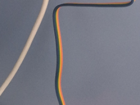
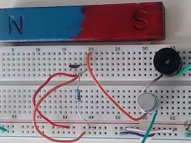
This was a one evening build. The device was built on a simple breadboard.

As a 1PPS source, I’m using my GNSS receiver.

The measured propagation delay on TTL output is only 4 ns:

The SN74HC244 buffer is a little bit slower, and the CMOS lines delay is 16 ns:

All channels are working synchronously, with no delays or ringing.

All measures are made with Saleae 8 channel logic analyzer:

Thanks for reading!
来源:1PPS distribution circuit – Oleg Kutkov personal blog
链接:https://olegkutkov.me/2021/02/28/1pps-distribution-circuit/
文章末尾固定信息


评论